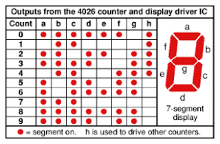
 The CD4026 is a decade counter with outputs for a 7 segment LED display (see table left). But those outputs can also be used to drive any old LEDs, and I discovered that simply cycling through numbers 0 to 7 at around 5 Hz created a rippling, flickering kind of effect on an LED bar that looked a little like the wick of a candle. Who knew — perhaps it would look good in a Jack O' Lantern. I decided to put one together, throwie-style.
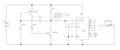
I had a notion to solder the chip to the back of the LED bar. But using only one chip meant that I would need to create an oscillator from discrete components with which to clock the counter. I found an unusual circuit for a complementary multivibrator, attributed to one J. C. Rudge, that had a low part count. It worked fine, with a very high duty cycle, although the resistor values seemed rather critical and I ended up varying the frequency by changing the capacitor. The schematic looked like this:
I put the circuit together dead bug style on a machined pin DIP socket. I started by gluing the transistors face to face, then bent their legs to the side and soldered what would become the 3 V line to the emitter of the BC557 and the clock line to the collector of the BC546. (Different transistors may have alternative pinouts which would change how to assemble the multivibrator.) With the transistors in place on the socket, then soldered on the other passive components one by one. I soldered wire links on the socket to create outputs for the 9th and 10th LEDs in the bar, then put in Ground and 3 V lines. Lastly, I dealt with the LED bar itself. I soldered a bare wire to connect all 10 cathodes, then cut off all the cathode pins except for two that would attach to pins 2 and 9 on the chip. I bent anodes 1 and 2 inwards and splayed all the others out. Then I connected anodes 1 and 2 to a couple of the other anodes — having 10 LEDs and only 8 outputs, a little duplication was in order. Finally I soldered on the LED bar having clipped off any superfluous pins off the socket.
I had intended to hot glue a coin cell holder to the bottom off the LED bar assembly and use it like a throwie. Unfortunately I had forgotten that ten LEDs require quite a lot more current than one! A couple of AA cells in a battery holder powered the candle just fine; 5 V made it a good deal brighter.
I salvaged a cardboard tube from a roll of kitchen foil and the kids helped me decorate it with shiny paper. The final touch was to diffuse the light by covering the LED bar in a couple of turns of bubble wrap before stuffing it inside the tube. Some time passed while I was staring at the Blinkenlights before I realized I was in a kind of trance.
Materials
CD4026 IC
10 segment LED bar 180 kΩ, 360 Ω, 39 Ω resistors
complementary small signal transistors (e.g BC546, BC557)
470 uF capacitor (preferably nonpolar) 2x AA cell and battery holder
Construction tips
This project is fairly Easy. It took me a couple of attempts to figure out a way of putting the multivibrator together. Soldering components freehand takes a bit of skill — one that I have yet to acquire, as you can see from my blobby efforts. The whole thing took me a couple of hours.


1 comment:
It seems not too difficult, but it also has some challenges. However, the blogger's final result is not very perfect, so it's just for fun. If you want to make a more perfect Halloween LED candle, you can refer to this website: <a href="It seems not too difficult, but it also has some challenges. However, the blogger's final result is not very perfect, so it's just for fun. If you want to make a more perfect Halloween LED candle, you can refer to this [url=https://www.flamelesscandle.shop/c/20/halloween-led-candles]Halloween LED Candles[/url]
Post a Comment