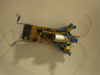
Powered by a solar panel, this miniature robot shuffles towards the light.
This project was a venture into BEAM robotics, a now seemingly defunct genre characterized by simple circuits with complex behavior. This autonomous, bug-shaped beast soaks up sunshine on its solar panel and converts it to bursts of movement on its tiny motors. LEDs acting as photodiodes bias the circuit so that the motor on the darker side is more likely to fire. This phototaxic movement orients the robot towards the light, giving it the name of "photovore" or light eater. The antennae act as tactile sensors: if the bug bumps up against an object on one side, it will move in the opposite direction next time the motors fire.
Instead of constructing the robot in the usual dead bug style, I decided to lay out the circuit on a piece of stripboard the same size as the solar panel. I like the way it looks, but the extra weight is no help for the tiny pager motors.
How the circuit works
Considering the small number of parts, there is a surprising amount going on in this circuit. The right hand side of the schematic provides the engine. Light hitting the solar panel creates a potential which charges the storage capacitor. When the voltage across the terminals of the capacitor reaches 2.7 V, the 1381J voltage detector triggers the transistor, which pulses the enable line of the 74AC240 chip. The two inverters connected end-to-end form an oscillator known as a bicore: when the power is toggled on by the enable line, the oscillator assumes the opposite state to what it had when the circuit was powered off. Mark Tilden named this toggling feature "Shok" architecture. The power-on state is also dependent on the voltage across the bicore capacitors, which is a function of the light hitting the photodiodes. Tactile sensors take the form of switches between the input of the oscillator circuit and the high voltage line. When the switch is close it forces that side of the bicore high, presetting the state of the oscillator on the next pulse cycle.
Materials
- 74AC240 inverting octal buffer
- pager motors (2)
- 6V 16mA solar cell
- 1381J voltage trigger
- BC337 NPN transistor
- Red LEDs (2)
- 220 nF (2), 1 uF, 2200 uF capacitors
- 100 kΩ multiturn trimmer resistor
- Fuse clips (to hold motors)
- Guitar strings (back legs)
Construction tips
The robot is Easy to make — if you can get the parts! Pager motors cost a lot more than they used to even a couple of years ago, and it is not easy to get hold of 1381s. A newly made robot will probably tend to veer off to one side: you will need to twiddle the trimmer resistor until it moves in straight lines. Adjustments are a lot easier with a multiturn trimmer. It is customary to decorate BEAM robots with strips of colored heat sink.


2 comments:
Lovely build and nice blog.
Wow, thanks oakkar! :-)
Post a Comment