Pan -- in a flash!
Like many people I like to keep in contact with friends and family using Skype or other video conferencing software. Usually they are more interested in seeing the kids than looking at me. The trouble is that the kids are a moving target. They can be wrestled into position for a second or two, but soon they will have wriggled off out of camera shot.
The solution was to mount the webcam on a servo. A servo is a motor with a feedback mechanism that allows accurate angular positioning. Servos are available from Radio Control outlets and hobby stores. Each one comes with a plastic "horn" which attaches to the motor shaft.
A little violence was needed to attach the webcam to the servo horn. I had to peel back the rubber covering on the base of the webcam so that I could screw into the plastic underneath. Then I gripped the servo in a heavy G-clamp and set it on top of a coffee can. Perhaps at some point I will rig up something a bit more decorative and adjustable.
Chip and easy servo tester circuit
Servos are controlled by a PWM (Pulse Width Modulated) signal. It's easy to breadboard a timer circuit to control the servo using a potentiometer. The circuit comprises a 555 chip plus a few passive components and can be set up on a mini breadboard. The component values below worked well for me, although servos do vary slightly in their specifications. Tayda is an inexpensive source of electronic bits in small quantities.
Do it with a microcontroller: Uno you want to
It is also straightforward to control a servo using an Arduino. Although hobby servos typically run off 5 VDC, the same voltage as an Arduino, their unpredictable current requirements means they need a separate power supply. The ground wires of the power supplies should be connected so that the servo and the Arduino have a common reference voltage.
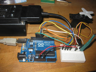
I had rigged up a Guitar Hero foot pedal to talk to an Arduino and this was a great way to use it. The picture below shows my Arduino Uno connected to the foot pedal's radio dongle and the servo and its power supply via a mini breadboard. The black jumper wire connects the grounds; the white jumper connects Arduino pin 9, the source of the PWM signal, with the yellow wire on the servo.
There was a slight niggle in that the software serial routines used in the Playstation controller library do not play nice with the current version of the Arduino Servo library. Fortunately they work perfectly with the old Arduino library that uses hardware PWM, and soon I had a working sketch.


No comments:
Post a Comment