Instructions for assembling Heart Shaped LED Chaser
What's the story?
It all started with a blinky Valentine's heart that I made for my beloved. So many people asked me if they could have one — especially after it was featured on MAKE magazine — that I decided to roll it out as a kit (available now from Tindie). Look here to see the schematic and some more pictures and stuff.
Kit contents
 |
| Alternative battery clip with switch (2x CR2032) |
 |
| 1x 100 KΩ trimmer resistor (200 KΩ in some kits) |
 |
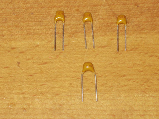
| 3x 100 nF capacitors 1x 1 μF capacitor (0.47 μF in some kits) |
Tools
These tools will come in handy:
In addition, you will need flux core solder. Lead-free solder is preferred because it is safer, especially around kids. (The PCB is completely lead free, by the way.) Take sensible precautions: wash your hands after touching leaded solder and clear the work surfaces of soldering debris.
Assembly Instructions
Insert the capacitors into the central Holes. The orientation of the capacitors does not matter, but the pitch does matter. The three 100 nF capacitors fit in the upper slots which have holes spaced 2.5 mm apart. The wider 1 μF capacitor fits between the 5 mm pitch holes. The capacitor values are marked below the holes.
Bend back wires on reverse of PCB. This helps stop the components from falling out when you are soldering them in place.
Solder the wires to the PCB. Heat the soldering iron to around 350 °F (175 °C). Briefly apply the tip of the iron so that it heats both the pad of the PCB and the bottom of the wire. Then touch the end of the solder wire to the tip of the iron. The solder will flow onto the hot metal surfaces.
After soldering the wires. they should look something like this.
Good solder joints have a shiny appearance. Cold (underheated) joints look stiff and grainy. Overheated joints can look blobby and may be discolored from burned flux. If a solder joint looks unsatisfactory, remove excess solder with solder wick or a solder pump, apply flux to help clean up, and resolder.
After checking that the solder joints are satisfactory, clip the wires flush to the surface of PCB.
Cutting the wires flush keeps things tidy and helps avoid shorts between neighboring joints.
Next insert the three 1 KΩ resistors on the right had side of the PCB. The orientation of the resistors does not matter.
Bend back the wires on the reverse of PCB.
Solder the wires to the board and cut the ends flush.
Insert the trimmer resistor toward the bottom of the board. Only one orientation of the three pins is possible.
Bend back the pins on reverse of PCB.
Solder the pins and cut flush.
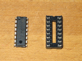
Insert 8 pin DIL socket top right. Orient the socket so that the little semicircular mark is toward the top of the PCB.
Soldering the DIL socket requires a little care because it is difficult to desolder if anything needs redoing. Solder 2 pins on opposite corners to secure the socket to the PCB.
Double check the socket is correctly oriented and flush to the PCB. If everything looks good, then solder the remaining pins.
Now do the same with the 14 pin socket. Notice the orientation of the sockets with the semicircular indentations toward the top of the PCB.
After soldering the sockets, you can cut the pins flush or just leave them as they are. The reverse of the board should look something like this.
Now insert an LED. The short leg (cathode) should be toward the bottom of the PCB.
Bend back the wires on the reverse of the PCB, solder, and cut the wires flush.
Now do the same for the other LEDs. They should all be oriented with the short leg (cathode) towards the pointy bottom of the PCB.
Bend back the pins on the reverse of the PCB, solder, and cut flush as before.
You have nearly finished!
Thread battery clip wires from back to front through upper holes. (One of the LEDs seems to have gone missing in this picture! Make sure that you have soldered all 10 LEDs.)
The red wire should go through the holes marked '+', 'Red'. The black wire should go through the holes marked '-', 'Black'.
Now thread the exposed ends of battery clip wires from front to back through lower holes and solder them to the pads on the reverse of the PCB. After soldering on the reverse of the PCB, gently pull the wires back through the upper holes. The double holes provide a measure of strain relief.
Finally, we need to insert the integrated circuits into their sockets. It will be a tight fit, so it may help to bend pins inward ever so slightly by pressing the side of the chip against a suitable surface. Take care when handling the chips because their CMOS circuitry is sensitive to static discharge. Ground your hands against a metal surface before touching the chips or use an ESD safe wrist strap.
Done! Below is a front view of the completed LED chaser. All it needs now is a battery!

Reverse view: a message for someone special. Order your kit today!


No comments:
Post a Comment